Control Module ABS 20 Technical Guide
![]()

This guide is targeted to the embedded systems developers who want to have a deep understanding of all the features and peripherals of the ABS 2.0 module for developing or debugging purposes.
The micro-controller used in ABS 2.0 is the tm4c1294ncpdt and is inside the evaluation board TM4C1294XL.
All the developed libraries were targeted to work with this specific micro-controller or with a compatible one like the tm4c129encpdt that is part of the evaluation board TM4C129EXL. For more information about these micro-controllers or their evaluation boards, please refer to http://www.ti.com/
The developed libraries were EEPROMMan, EthernetMan, GPIOMan, MensajesMan, MultiUDPMan, Nokia_5110, ProcesaMan, RestMan and WatchdogMan, all these are going to be explained in detail in the following sections.
EEPROMMan library
This library contains all the functions needed to save and retrieve information from the EEPROM memory of the micro-controller.
The EEPROM of the tm4c1294ncpdt is only accessible 32-bit word by word, for that reason this library implements functions that access to the 4 bytes but masking it byte by byte, getting the feel of byte operations.
The information in the EEPROM memory follows the diagram shown below:

The first two bytes of the EEPROM will contain the EEPROM position of the last beam to which the module pointed, this is needed for the GETC, GETB and so that when resetting the module, avoid to cause a pin's state value change while the RF is activated.
The following two bytes of the EEPROM contains the total number of beams of the current experiment, this is useful for verifying the packages that are received by the module.
The next 125 bytes of the EEPROM contains 1000 flags for the beams, one bit per beam, used for the module to keep track of exactly what beams of the current operation has been sent and to avoid accessing to a non-sent beam if the SIR sends a change beam operation to that beam before sending the respective package. These flags are active high, that means there is a 1 when the beam is accessible and a 0 when is not.
Starting in the address n° 129, after the beam flags, it will save all the beams information, the length of this part is variable and depends of how many beams has the current experiment.
And for the last, the last address of the EEPROM has a GPIO flag, a flag used to indicate when after a change of beam operation the monitoring pins read a value different than the expected. The flag takes the value 1 when is active and 0 when not.
Another feature, blocking the EEPROM with a password, was performed to avoid undesirable accesses to the EEPROM. The programmed password was the array {1,2,3}. The feature was implemented by keeping blocked the EEPROM while not used, unblocking it with the ROM function ROM_EEPROMBlockUnlock before accessing it and blocking it again with the ROM function ROM_EEPROMBlockLock after the respective EEPROM operation.
The functions that this library provides are the following:
void Conf_EEPROM(void) : This function enables the EEPROM peripheral, configures its protection with password and performs an error checking.
void Writting_beams(char* beams,uint8_t id): This function takes the corresponding beams to each module and the ID of the package sent to write the beams in the respective EEPROM address. It's good to highlight that the saved value is not exactly the beam sent by the SIR but the real beam information, that is the sent value minus 33.
void Read_Beam(uint16_t position): This function takes a position, reads the respective EEPROM address and writes it in binary format in the control GPIO pins.
void ToBinary(uint8_t value, char cadena[7]): This function is used by the previous function to get the binary format used to write the control GPIO pins.
uint8_t Read_EEPROM(uint16_t position): This functions reads the EEPROM address described by position by first unlocking the EEPROM, reading the 32-bit EEPROM, masking it, locking the EEPROM again and finally returning the result value.
void Write_EEPROM(uint32_t position, uint8_t value): This functions writes a value to the EEPROM address described by position by first unlocking the EEPROM, reading the 32-bit EEPROM, masking it, adding the value shifted, writing the result and finally locking the EEPROM again.
uint32_t GetActualBeam(): This function is a special version of the Read_EEPROM function, because it performs a reading of two specific addresses (0 and 1) of the EEPROM and returns a concatenated value that is the position of the last beam that the module pointed.
void SaveActualBeam(uint32_t pos): This function is a special version of the Write_EEPROM function, because it performs a writing of the position of the last beam that the module pointed to two specific addresses (0 and 1) of the EEPROM.
uint32_t GetNbeamsTotal(): This function is a special version of the Read_EEPROM function, because it performs a reading of two specific addresses (2 and 3) of the EEPROM and returns a concatenated value that is the total number of beams of the current experiment.
void SaveNbeamsTotal(uint32_t nbeamstotal): This function is a special version of the Write_EEPROM function, because it performs a writing of the total number of beams to two specific addresses (2 and 3) of the EEPROM.
Should be take in account that before performing any write operation to the EEPROM, the watchdog timer was disabled to avoid this slow operation to trigger a reset.
EthernetMan library
This library contains all the functions needed to configure the Ethernet and multicast communication of the module.
This library contains only the two following functions:
configEthernet(void): Function that initialize the Ethernet controlling and configure the ip, dns, gateway, subnet mask and the multicast group that the module are part of. If the developer wants to change any of these parameters should do it here.
void printEthernetData(void): Prints the Ethernet controller data only when the module is on DEBUG_MODE as will be explained in the MensajesMan library.
Should be take in account that no mac address programming is performed in this library, the mac address used to configured the Ethernet controlled is read from user registers inside the initialization of the Ethernet library, that means that if for example the micro-controller of the module has been reseted by unlocking its DEBUG port and no mac address was committed the Ethernet library is not going to work. More details on how to perform an unlocking of the DEBUG port, why it is useful and how to program a mac address will be explained in Watchdog Section.
GPIOMan library
This library contains all the functions needed to configure the control and monitoring GPIO pins, configure the GPIO interrupts, its interrupt handler and other useful functions. This library contains the definition of important constants in its header such as the number of module (from 1 to 64) and the exact GPIO pins used to each control or monitoring pins.
This library is comprised of the following functions:
void configPins (): Configures the control GPIO pins as outputs and the monitoring as inputs with pull-down resistors.
void ConfigGPIOInterrupts(): Configures the GPIO interrupts for the pins used in the GPIO E, C and D as monitoring pins and register its handler. Before configuring any interrupt, the GPIO interrupts are disabled to let perform a custom interrupt configuration each time a new beam has been sent. Right now the interrupt configuration is fixed and not depends on the current beam because of lack of development time.
NOTE: Even when the GPIOs interrupt are configured for each pin, the micro-controller doesn't support an interrupt service routine for each pins. That means the interrupt controller only knows what port triggered an interrupt but not exactly what pin did it.
void EnableGPIOInterrupts(): This function enables the GPIO interrupts, should be called after calling the previous function. It enables the interrupt at interrupt controller and peripheral levels.
void DisableGPIOInterrupts(): This function disables the GPIO interrupts, should be called after calling the previous function. It enables the interrupt at interrupt controller and peripheral levels.
void GPIOIntHandler(): The interrupt service routine for all the GPIO pins, the only action done here is saving the interrupts flag to later perform a POST to the SIR with the information of which GPIO port triggered the interrupt.
void SendGPIOInformation(): This functions reads the variables that contains the GPIO interrupts flags and if it is active, check the respective GPIO port to see which pins are not the expected and perform a POST with the information collected.
NOTE: It is good to highlight that the expected read state for each monitoring pins is the logical not of the state of the respective control pin.
- void SendGPIOInformation2(): This function is pretty similar than the previous one, but instead of using the variables with the GPIO interrupt flags, use the flag in the last EEPROM position that is saved when after a change of beam operation the monitoring pins states doesn't match to the expected values. This function unlike the previous one sends information about all the monitoring GPIO ports.
MensajesMan library
This library contains functions for printing text information on a serial console and displaying the ethernet and current beam information on a NOKIA LCD 5110. It's very useful for debbuging.
This library took too much importance when the watchdog peripheral was enabled and set with a 1 ms period because the printing of continuous large texts was slow enough to trigger a watchdog reset. To avoid the undesirable watchdog reset, before performing any printing to the serial port the watchdog peripheral is reseted, and configured again after the print operation has finished.
To accomplish the overload of the printing operations a lot of custom printing function were defined, specifically for ints, chars, array of chars, constant array of chars and Printables, such as the IPAddress class.
This library also performs the option to disabling all the serial printings when the module has finished its development process, that commenting the line #define DEBUG_MODE in its header.
It's needed to highlight that when debugging the user should use only the DEBUGprint and DEBUGprintln functions defined here instead of the raw Serial print because the first ones doesn't trigger a watchdog reset but the last ones does it as mentioned before.
Aside of the functions used to overload the printing, there are other three functions defined here:
configSerial(): Configures the serial port with a baud rate of 115200 bauds.
PrintInfo(): Prints to serial port information about the multicast configuration
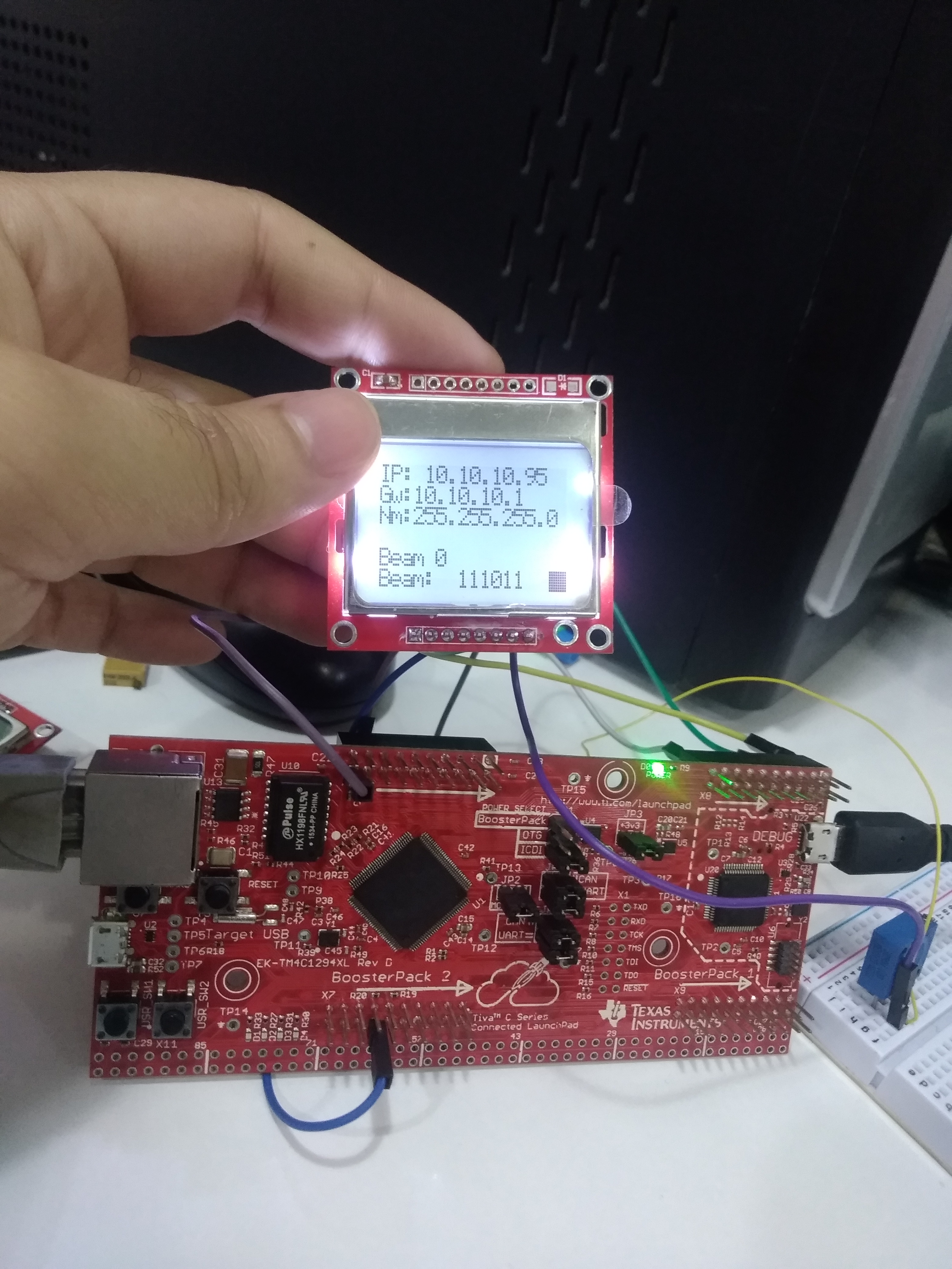
ShowModuleInformationLCD(): Prints on a LCD information about the Ethernet configuration, the number of the current beam and the beam itself. It also shows a pulsating square to let user know if the module is currently running.
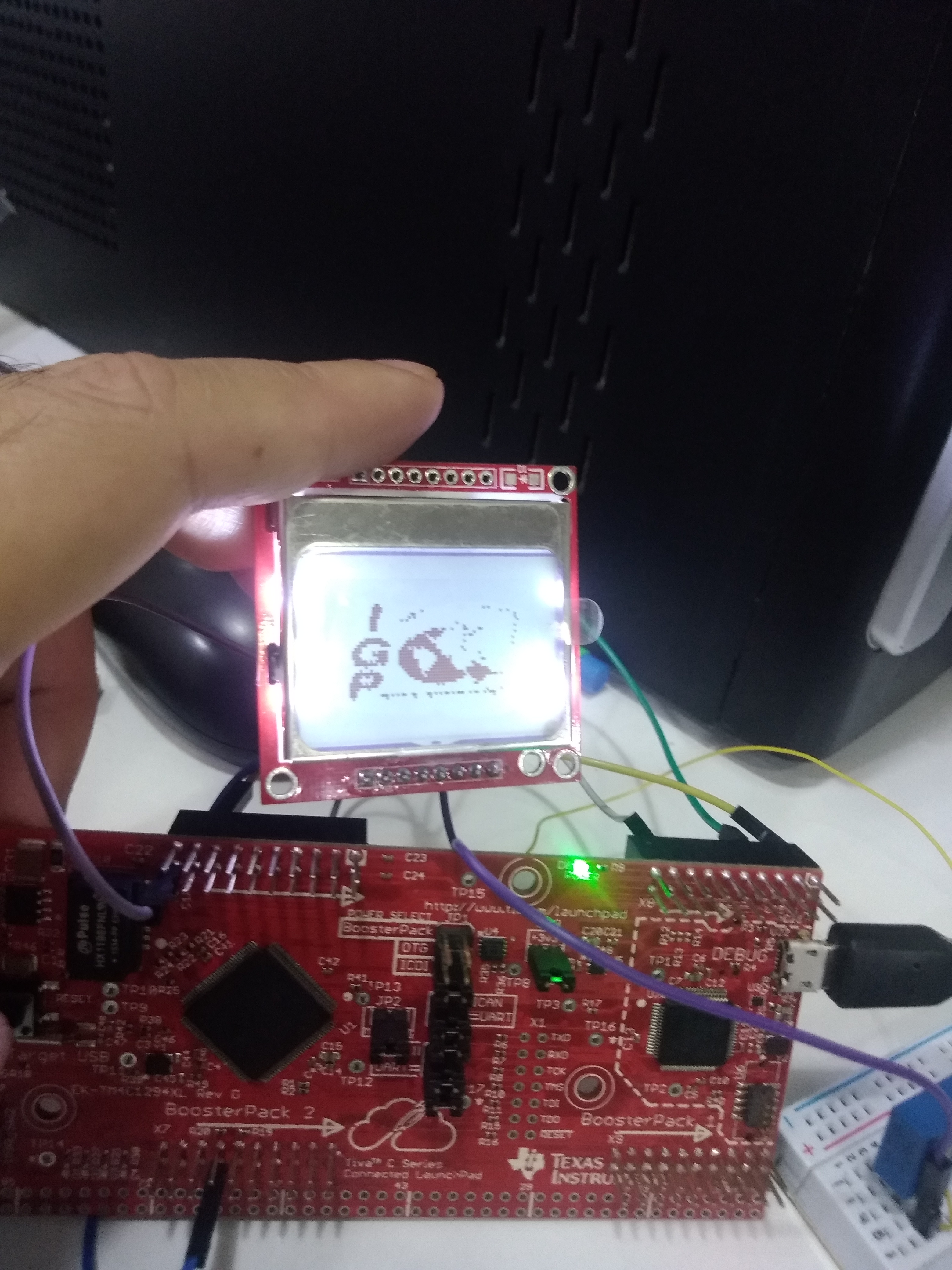
NOTE: The header of this library also contains a array of uint8_t called IGP_logo that corresponds to a binary image version of the IGP's logo that fits in the 84 x 48 pixels of the Nokia 5110 LCD.
MultiMan Library
This library implements the function used to start the multicast communication, receive a multicast package, show information, process it and send a reply.
The functions defined here are:
void configMultiUDP(): Starts the multicast communication by using the port portMulti that is 10000 in this case.
void server_MultiUDP(): This function checks if there is a sent package by using a parsing function, sends information about the GPIOs, and if there is a package available, read it into a buffer, process the package received and sends a response to the SIR that contains the information requested. It also prints information about the packages received if the module is in DEBUG mode.
Nokia_5110 Library
This library contains the functions used to configure the SSI interface of the micro-controller to communicate with the a Nokia 5110 LCD, perform actions as clearing the LCD and displaying information in the screen.
The functions implemented in this library are described below:
void ConfigSSIInterface(): Configure the SSI0 interface of the micro-controller as a master to communicate with the LCD.
void SetCursor(uint8_t x, uint8_t y): Set the cursor in the position given by (x,y), x must be an integer in [0,83] and y must be an integer in [0,5].
void ClearLCD(): Clears the entire LCD display.
void ShowImage(const uint8_t image[]): Shows in the display the 84 x 48 binary version of an image that is in the array of uint8_t.
void ResetLCD(): Performs a reset for the controller of the Nokia LCD, it is recommend by the fabricator to ensure a correct behavior of the LCD.
void EnableSlave(): This function actives the chip enable pin of the Nokia LCD controller, so it starts listening to its SPI port.
void InitLCD(): This function performs any initialization actions recommended by the fabricator.
void PrintChar(uint8_t x, uint8_t y, char character): This function displays a character in the given position.
void PrintStr(int x, int y, char string []): This function displays a message starting in the given position. If the message overpass the LCD limits, it starts writing on the first position of the LCD until it has printed all the message.
void PrintSquare(uint8_t x, uint8_t y): This function prints a square in the lowest left corner of the LCD. It's used to get the pulsating square that indicate that the module is running.
ProcesaMan Library
This library contains all the functions used to process a package that has been received by multicast.
This library is comprised of:
void SplitFrame(char *frame): This function splits a package according to the command that is in the package.
void Process_Petition(char *rx_buffer, char *tx_buffer, uint32_t packet_size): This functions process the package according to the command and forms a response to be sent to the SIR.
void Change_Beam(char *puntero_char): This is the function called the previous function detects a change of beam command. It performs a Read_Beam and saves the position of the beam requested in the EEPROM. It also checks if the monitoring pins coincide with the control pins and according to that sets the GPIO flags in the last address of the EEPROM.
void Initial_Beam(): This function is called every time the module is reseted, it reads the first two bytes of the EEPROM that contains the position of the last beam that the module pointed to and read this EEPROM address obtaining the value of the beam that is used to perform a change of beam operation. Because of the speed of the micro-controller and the implementation of this feature, if the module is reseted by the watchdog it should recover its last state in less than 4 ms approximately avoiding a that relays notice a change of control pins states when the RF is on.
void SetBeamFlags(uint8_t id, uint8_t beams_package): This function is called every time a new package with a write command is processed, it sets in the EEPROM the flags of the respective beams. The beams_package parameter is used to customize how many flags are going to be set according to how many beams the package has.
NOTE: Because all the packages except the last package have 20 beams only the id of the respective package and the number of beams of this package are needed to know what beams has been sent.
void InitializeFlags(): This function initialize all the beam flags to 0, it is called an ID 0 package is received.
To ensure correct behavior of the module before sending package of any ID, it should be sent the package of 0 to reset the beam flags.bool CheckFlag(uint32_t nbeam): This function checks and returns if the beam requested by a change of beam operation has been set or not.
bool CheckCurrentBeam(uint32_t current_beam): This function checks and returns if the beam correspond to the values read by the monitoring pins.
void FromDec2BinStr(char* bin_str,uint8_t beam): This function creates a string that containts a binary version of a beam. It is used to display the beam information on the display LCD.
RestMan Library
This library has only two functions, used to posting a message in the SIR and reading its reply.
- void PostIssueMessage(char* message): This function tries to connect to the SIR with a timeout of 500 us, it loops until the connection has accomplished, after the module connects to the SIR, it sends a package with a HTTP string that has inside the message to be sent. Right after the module loops until it gets the SIR's reply. When the reply is got, it is read and the connection is stopped.
After doing some tests of these features with the watchdog configured to 1 ms period, it did noticed that sometimes the HTTP string was sent but didn't get the SIR server so the SIR didn't reply and module loops forever. To solve this problem, a variable called received was used, if the reply didn't come when the waiting has timeout, this variable is set allowing to trying again to sent the message and wait for the answer until it completes correctly.
- int ReadReplyMessage(EthernetClient client, char* buffer, int n): This function reads until n bytes of a reply from a Ethernet connection and saves it in a string.
Watchdog Library
Because of the long time that all the modules are going to be operating without supervision for long experiments, it was implemented a watchdog timer that reset the module if there was any problem that made the module hang up. The watchdog timer sent a reset signal to the system control if it goes two times from the value programmed by the user to 0. The first time the watchdog gets 0 an interrupt flag has triggered and the micro-controller executes an interrupt service routine if there is one.
The watchdog timer counter should be reseted to its programmed value before gets 0 at any part of the program, to get that there is alot of ResetWatchdDogTimer calls inside all the libraries and Energia sketch. If the program hangs up it will not reset the watchdog timer counter and therefore will generate a reset signal.
NOTE: It is a bad practice to reset the watchdog timer by using an interrupt of a timer of higher frequency because even if the main program fails the timer could trigger an interrupt and reset the watchdog timer preventing thus the reset of the module.
The functions that comprise this library are:
void ConfigWatchDog(void): Configure the watchdog timer to trigger a non-maskable interrupt when timeout for the first time and to reset the entire micro-controller when timeout the next time. The counter was programmed to count until 1 ms.
void ResetWatchDogTimer(void): Reloads the programmed value to the watchdog counter to preventing from reseting the module.
bool CheckResetWatchDog(void): Reads the registers of the system control that have information about the cause of the reset and returns true if the cause was the watchdog timer. Before returning this flag are cleared because it's not cleared by reading it.
void DisableWatchDog(): Because a prior try to disable the watchdog timer ended in a weird and unexpected failure of the EEPROM, this function was implemented as the fabricator recommend, that is by resetting the entire peripheral.
void EnableWatchDog(): Only performs a call to the ConfigWatchDog function.
Tips for working with WatchDog Timer
When watchdog timer is configured with a relative fast period like 1ms, some slow operations like the programming operation of the Energia IDE trigger a watchdog reset, to avoid that the watchdog timer should be configured to stall during debug events. This is configured by using the function ROM_WatchdogStallEnable.
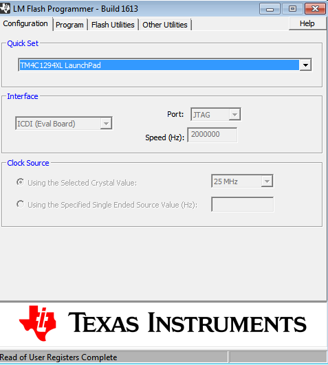
When the program enters into a loop of resets when an early slow operation triggers a watchdog reset, the Energia IDE is going to face problems to connect to the board. This could be solve by unlocking the DEBUG port, this is a feature of some programmers like UniFlash or LM Flash Programmer. Uniflash has a Linux version but its unlocking feature has a problem of missing libraries that is not solved by TI by now. By the way, LM Flash Programmer works pretty well but is designed for Windows OS only. For that reason I strongly recommend that when the watchdog makes the connection to the Energia difficult to get, it should be unlocking the port by using LM Flash Programmer.


After unlocking the DEBUG port following the LM Flash instructions, the user registers that contains the MAC address will be emptied and therefore any kind of communication that use the Ethernet controlled will not work until these registers are programmed again.
To program a MAC address in the module the user should write the mac address an click on program mac like the image above, and checking the commit mac address option when a permanent programming is desired and unchecking it when not.
If the MAC address was commit, it cannot be reprogrammed again until a new unlocking of the DEBUG port is perfomed. And if it is not commit then the MAC address only will be accessible until the next reset.